Application
HDPE Pipe for Agricultural Subsurface (Tile) Drainage & Land Drainage (2026)
Coiled, perforated corrugated HDPE plowed into a field in a single pass is why drainage that once took a season of hand-laid clay tile now takes an afternoon — and why drained fields yield more.
Dr. Wei Liu, P.E.
Senior Engineering Manager · Primepoly
Published: Jun 8, 2026
Updated: Jun 8, 2026
14 min read
Subsurface drainage — "tile drainage" — is one of agriculture's highest-return investments, and corrugated HDPE is what made it fast and affordable. Buried perforated pipe pulls excess water out of the crop root zone, lowering the water table so roots can breathe, machinery can travel, and yields climb. The reason it's now routine rather than a season of back-breaking work is the pipe: coiled, perforated, flexible HDPE that a GPS-guided plow lays in a continuous single pass where clay and concrete tile once had to be hand-laid in short rigid sections. This guide covers why it works and how to design it — coefficient, depth, spacing, grade and sizing.
What subsurface drainage is — and why it raises yields
Subsurface drainage is a network of buried perforated pipe that removes excess water from the crop root zone, lowering a high water table to a target depth. The goal is to drain the upper root zone within about 48–72 hours of a heavy rain, so roots aren't sitting in waterlogged, oxygen-starved soil. The payoff is large and well documented: better and more consistent yields, earlier and longer field access for machinery, a longer growing window and improved soil aeration. The cost of not draining is just as real — with the water table sitting only 15–20 inches below the surface, studies show wheat yields dropping around 40% and sugarbeet around 30% of potential. Drainage turns a marginal wet field into a reliably productive one.
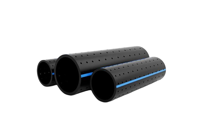
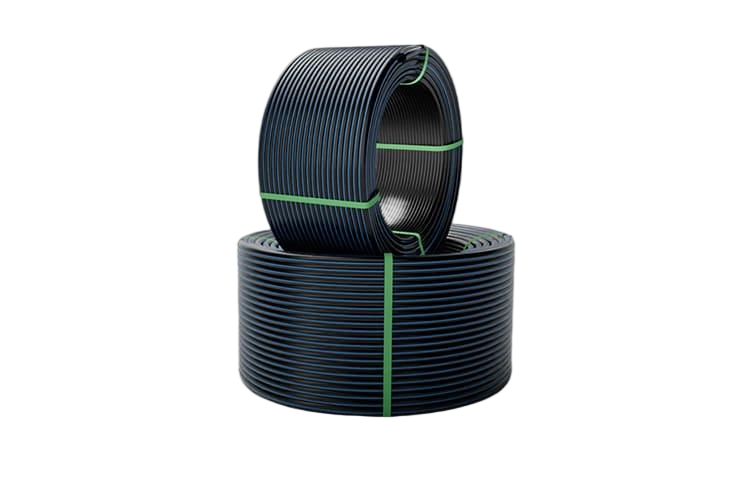
Why corrugated HDPE replaced clay & concrete tile
Clay and concrete "tile" came in short, rigid sections that had to be hand-laid with many joints — slow and costly. Corrugated HDPE changed the economics: it's light, ships in long coils (from 100 feet up to several thousand depending on diameter), is corrosion-proof, and is flexible enough that a GPS-guided drainage plow lays it continuously in a single pass with the perforations already moulded in. Two forms cover the system. Single-wall corrugated pipe (corrugated inside and out) is flexible, coilable and low-cost — the dominant choice for laterals, with a Manning's roughness around 0.015–0.020. Dual-wall pipe (corrugated outside, smooth inside) has higher flow capacity (n ≈ 0.012) and is used for the mains and submains that carry the collected water.
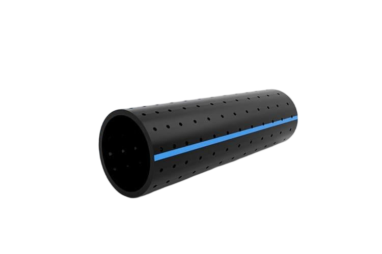
Perforations & the geotextile sock
Water enters the pipe through moulded perforation slots in the valleys of the corrugations. In stable soils that's all you need, but in unstable, sandy or silty soils the fine particles can wash in through the slots and clog the line — so a geotextile "sock" or filter wrap is added around the pipe to block the fines while letting water through. The decision is driven by a velocity criterion: a minimum flow velocity of about 0.5 ft/s is fine in stable soils, but where fine sand or silt can enter you design for about 1.4 ft/s to keep the line self-cleansing, and you add the sock. Getting this right in sandy ground is the difference between a drain that lasts decades and one that silts shut in a few seasons.
Designing the system: coefficient, depth, spacing & grade
Four parameters define a subsurface drainage design, and the table gives the verified ranges. The drainage coefficient (DC) is the depth of water to remove per day — about 1/4 to 1/2 inch per day for ordinary field crops on mineral soil, rising to 3/4–1 inch (and up to 1.5) for high-value specialty crops, organic soils or systems with surface inlets. Drain depth is typically 3 to 4 feet. Drain (lateral) spacing depends heavily on soil permeability: as close as about 40 feet in heavy clay, widening to 120–300 feet in permeable sandy soils. And the minimum grade is about 0.08–0.1% (a foot of fall per thousand feet) — steeper where sediment may enter, to hold a self-cleansing velocity. Get the coefficient and the soil-dependent spacing right and the rest follows.
| Parameter | Typical value |
|---|---|
| Drainage coefficient — field crops, mineral soil | 1/4 – 1/2 in/day (3/8 common midpoint) |
| Drainage coefficient — specialty / organic / surface inlets | 3/4 – 1 in/day (up to 1.5) |
| Drain depth | ≈ 3 – 4 ft (deeper in sandy soils) |
| Drain (lateral) spacing | ≈ 40 ft (heavy clay) → 120 – 300 ft (sandy soils) |
| Minimum grade | ≈ 0.08 – 0.1% (1 ft fall per 1,000 ft) |
| Manning's n | single-wall ≈ 0.015–0.020; dual-wall ≈ 0.012 |
Sizing the pipe & system layout
Pipe diameter is sized from the area drained times the drainage coefficient, against the pipe's capacity at the available grade and roughness. The layout runs from small laterals (commonly 3–6 inches) that collect water across the field, into submains, into larger mains (8–18 inches) that carry it to the outlet — a gravity outlet to a ditch or stream where there's fall, or a pump/lift station where there isn't. To put numbers on it: at a 0.1% grade and a 1/4-inch-per-day coefficient, a 4-inch single-wall lateral drains roughly 5 acres, while an 18-inch smooth main can handle on the order of 400 acres. Free online pipe-capacity and spacing calculators from the land-grant universities make the sizing straightforward once the coefficient and soil are set.
Standards, and an honest material comparison
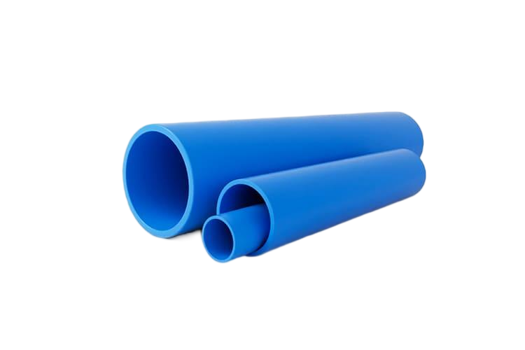
Corrugated PE drainage pipe is made to ASTM F667 (3–24 inch) and F405 (3–6 inch), and to AASHTO M252 (3–10 inch) and M294 (12–60 inch); dual-wall smooth-interior pipe falls under ASTM F2306. The table compares the materials honestly. Corrugated HDPE is the lightest, coilable, fastest to install and corrosion-proof — the modern standard for laterals — with the one trade-off of a rougher bore than smooth pipe (addressed by using dual-wall for mains). Clay and concrete tile is durable but heavy, rigid, joint-heavy and slow to lay, and concrete can degrade in acidic or sulfate soils; it's now largely legacy. Smooth-wall PVC has good hydraulics and is used where structural strength or specific fittings are needed, but it's heavier-handling and pricier per foot than coiled HDPE for long agricultural laterals.
| Material | Pros | Cons |
|---|---|---|
| Corrugated HDPE | Lightest, coilable, fastest to plow in, corrosion-proof, flexible, lowest installed cost | Rougher bore than smooth pipe (use dual-wall for mains) |
| Clay / concrete tile | Durable, historic | Heavy, rigid, joint-heavy, slow/costly; concrete degrades in acidic/sulfate soils — now legacy |
| PVC (smooth / corrugated) | Smooth bore (good hydraulics), rigid, strong | Heavier handling, pricier per foot than coiled HDPE for long ag laterals |
Smarter drainage: controlled drainage & nitrate reduction
The modern best practice worth designing in is controlled drainage (drainage water management, NRCS Conservation Practice 554). A water-control structure with a stackable weir raises the effective outlet elevation, so the field holds water when drainage isn't needed — over winter, or in a dry spell — and releases only the excess. Because it cuts the total volume of drainage outflow, it also cuts the nitrate-nitrogen carried off the field: Iowa's Nutrient Reduction Strategy credits about a 33% average nitrate-N reduction, and Ohio studies show 20–40% less annual discharge. It's best suited to very flat fields (under about 1% slope). On the right ground it turns a drainage system into a water-and-nutrient management tool — an increasingly important selling point.
5 common design & installation mistakes
- Using the wrong drainage coefficient — sizing for field crops where specialty crops or surface inlets demand 3/4–1.5 in/day.
- Spacing the laterals too wide in heavy clay — clay needs ~40–70 ft; sandy-soil spacing leaves wet strips and slow drawdown.
- Inadequate grade — below ~0.08–0.1% the line won't self-cleanse and silts up.
- No geotextile sock in sandy or silty soils — fines wash through the slots and clog the pipe.
- A poor outlet — undersized, submerged or eroding, or missing the pump/lift station on no-fall ground, backs the whole system up.
Glossary
- Subsurface (tile) drainage
- A network of buried perforated pipe that removes excess water from the crop root zone, lowering the water table to a target depth.
- Drainage coefficient (DC)
- The depth of water removed per day a system is designed for — ≈ 1/4–1/2 in/day for field crops, more for specialty/organic soils.
- Drain spacing
- The lateral spacing, set by soil permeability — ≈ 40 ft in heavy clay out to 120–300 ft in sandy soils.
- Single-wall vs dual-wall
- Single-wall corrugated (n ≈ 0.015–0.020) for flexible coilable laterals; dual-wall smooth-interior (n ≈ 0.012) for higher-flow mains.
- Geotextile sock
- A filter wrap around the pipe in sandy/silty soils that blocks fine sediment from entering the perforations while passing water.
- Controlled drainage (NRCS 554)
- A water-control structure that raises the outlet elevation to retain water when drainage isn't needed — cutting nitrate-N loss ~33%.
References & standards
- [1]University of Minnesota Extension — Designing a subsurface drainage system (coefficient, depth, spacing, grade)
- [2]NDSU Extension — FAQ about subsurface (tile) drainage (spacing & yield data)
- [3]University of Illinois — Illinois drainage guide — subsurface drainage
- [4]ADS — Single-wall corrugated HDPE pipe (ag drainage)
- [5]ASTM International — ASTM F667 — large-diameter corrugated PE pipe & fittings (3–24 in)
- [6]Transforming Drainage — Controlled drainage / drainage water management
- [7]Michigan State University Extension — Drainage pipe-capacity & sizing calculators
Frequently asked questions
Need expert advice on your project?
Our engineering team helps utilities, contractors and EPCs specify the right pipe material and SDR for their project. Get a no-obligation technical consultation.
Talk to an engineerRead next
13 min read
HDPE Corrugated & Double-Wall Pipe for Drainage, Stormwater & Culverts (2026)
14 min read
HDPE Pipe for Stormwater Detention, Retention & Infiltration Systems (2026)
13 min read
HDPE Pipe for Irrigation: Drip, Sprinkler & Farm Mains (2026)
13 min read
HDPE vs PVC for Drainage & Sewer: Which Pipe for Gravity, Non-Pressure Systems? (2026)
13 min read
HDPE Pipe Hydraulic Design & Flow Capacity: Sizing, Head Loss & Velocity (2026)
Explore further
Related applications, material comparisons and country buying guides selected for this topic.