Application
HDPE Pipe for Marine & Sewage Outfalls and Seawater Intakes: Float-and-Sink, Ballast & Diffusers (2026)
Fuse a kilometre of pipe on the beach, float it out full of air, then flood it from one end so it lays itself onto the seabed in a slow S-curve. HDPE is the only material that makes that routine.
Dr. Wei Liu, P.E.
Senior Engineering Manager · Primepoly
Published: Jun 8, 2026
Updated: Jun 8, 2026
15 min read
A sea outfall is one of the most dramatic things you can do with a pipe: fuse it into a continuous string a kilometre long on the shore, cap the ends, float the air-filled line out over its alignment, then flood it slowly from one end so it sinks gently onto the seabed in a travelling S-curve. HDPE is the material that makes this routine — it doesn't corrode in seawater, its fused joints are monolithic, and its flexibility is exactly what lets it lay itself down without kinking. This guide covers the why and the how, with the parts competitors leave out: the controlled-sinking physics and the ballast numbers.
Why HDPE is the default for marine outfalls & intakes
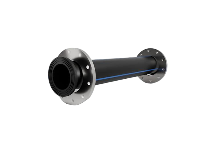
The case for HDPE in the sea is overwhelming and starts with corrosion. HDPE doesn't corrode in seawater and shrugs off the chemistry of wastewater and brine, so there are no coatings and no cathodic protection to maintain — the failure mode that plagues steel and ductile iron simply doesn't exist. On top of that, butt fusion makes monolithic, leak-free joints as strong as the pipe wall, so strings of 500–600 metres are fused onshore (and, famously, plugged sections have been towed over a thousand nautical miles by sea). Its flexibility conforms to the seabed and absorbs wave action and settlement, and the smooth bore and 50–100 year life seal the deal. Sizes run from around 150 mm up to outside diameters of 3,500 mm.
How a sea outfall is built: the float-and-sink method
The signature method is float-and-sink (controlled submersion). The string is fused onshore into one continuous, air-filled, sealed pipe; concrete ballast weights are clamped on at calculated spacing; the still-buoyant line — buoyant because the trapped air keeps its average density below seawater despite the concrete — is floated out over the alignment. The seaward end is anchored and held under controlled pull-back tension, then water is admitted at the shore end while air is bled off at the far end. The flooded portion sinks while the still-air-filled portion floats, and the transition rides down in a gentle S-curve — an overbend near the surface and a sagbend toward the bed — laying the pipe progressively onto the seabed from one end. Sinking is timed to slack water.
The physics of controlled sinking: buoyancy, air pressure & the S-curve
The descent is a balance: the net downward weight of the flooded section versus the buoyancy of the still-air-filled section, mediated by the internal air pressure and the end pull tension. Engineers hold a slight internal air over-pressure throughout the sinking, which does two jobs — it resists hydrostatic collapse of the large, thin-walled pipe at depth, and it meters how fast water advances down the bore, controlling the sinking velocity. That velocity has to be kept low and steady so the bend radius in the sagbend stays above the pipe's minimum allowable radius. The three levers the designer actually controls are the SDR (wall stiffness), the ballast spacing, and the internal air pressure plus end tension — get those right and the pipe lays down smoothly.
Ballast weights: degree of loading / offset weighting (with numbers)
Concrete ballast is the most misunderstood part of the topic, because the industry expresses it as a percentage — the "degree of loading" or "offset weighting" — defined as the percent of the empty pipe's buoyant force that the ballast cancels. So 100% means the ballast exactly cancels the buoyancy of the fully air-filled empty pipe (the empty, ballasted pipe is neutrally buoyant — the threshold for staying down when empty); below that it floats when empty, above it sinks even when empty. The crucial practical limit: if the required offset exceeds about 95%, you can no longer float the pipe out unaided and must add external floats or pontoons. And the weighting is graded along the route, not uniform — the table shows a real example. Two separate checks must both pass: floatability when empty (to tow it out) and on-bottom stability when water-filled (so it neither floats up nor walks along the bed under wave and current drag).
| Offset weighting | What it means | Where used |
|---|---|---|
| 50% | Cancels the buoyancy of a half-air-filled pipe — floats when empty | Not a stable in-service value alone |
| 100% | Neutrally buoyant when empty — the threshold to stay on the bed | Calm, deep, stable seabed section |
| 110% | Negatively buoyant even when air-filled | ~1,000 ft out from shore (moderate wave/current) |
| 150% | Heavier — extra margin over a local rise | Local seabed rise or higher-current stretch |
| ~300% | Very heavy ballast against breaking-wave & current forces | Surf / shore zone (highest energy) |
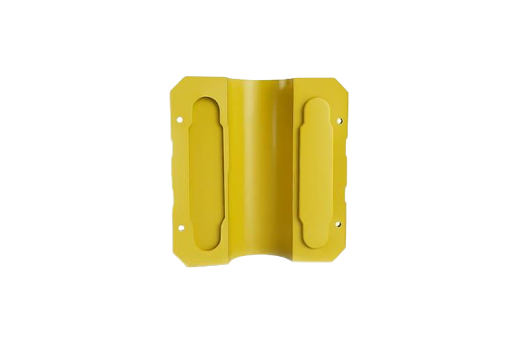
Ballast collar spacing & on-bottom stability
Ballast comes as split, bolted concrete "saddle" collars clamped around the pipe, typically holding it about a quarter-diameter above the seabed on the collar feet. Spacing scales with pipe size — roughly 5–10 ft for pipe up to 12 inches, 7–15 ft for 12–24 inches and 10–20 ft for 24–63 inches (PPI Handbook Ch. 10) — and high-density concrete coatings run around 190 lb/ft³. Real projects use hundreds of bespoke collars: the Severn Estuary outfall used 260-plus collars on a 1.4 km line, individual collars around 1.8 tonnes. On-bottom stability is the in-service check: the submerged weight of pipe plus ballast must exceed buoyancy with a margin and resist the wave and current drag and lift, which is exactly why the offset is graded up in the high-energy surf zone.
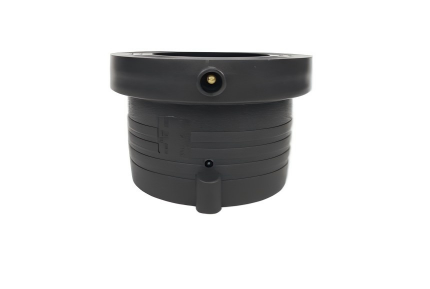
Diffusers, duckbill valves & the negatively-buoyant brine twist
The business end of a sewage or brine outfall is the diffuser — a terminal section with multiple ports or risers that break the discharge into many small jets to multiply the initial dilution (adding a multiport diffuser has raised measured dilution by an order of magnitude). Elastomer duckbill check valves fit on the ports: they open under flow and seal at low flow, keeping seawater, sediment and marine growth out, and raise jet velocity for better dilution across the flow range. Brine from desalination flips the logic: SWRO concentrate is denser than seawater, so it forms a negatively-buoyant jet that sinks and spreads along the bed — the ports are angled upward (often cited around 30°) to fire the dense jet up so it entrains seawater before falling back, the opposite of a buoyant-sewage diffuser. Designing a brine diffuser like a sewage one is a classic error.
Seawater intakes: screened heads for desal, cooling & aquaculture
The same float-and-sink HDPE technology runs in reverse for seawater intakes serving desalination plants, power-station cooling and aquaculture. The offshore end carries a screened intake head or tower with a coarse screen and a low through-screen velocity (typically around 0.1–0.15 m/s) to minimise impingement and entrainment of marine life. Everything that makes HDPE good for an outfall makes it good for an intake — corrosion immunity is decisive for permanent seawater service, and the fused, flexible string installs the same way. An intake is, in engineering terms, an outfall with a screen on the end instead of a diffuser.
HDPE vs steel, ductile iron, GRP & concrete
The honest comparison comes down to corrosion, joints and installability. HDPE is immune to seawater, fuses into monolithic leak-free strings, and its flexibility is what enables float-and-sink — its costs are that buoyancy requires ballast engineering, its lower stiffness needs buckling and ovality control on big-SDR pipe, and it has a lower pressure ceiling than steel. Concrete-coated steel is stiff and strong but corrodes (coating disbondment is the classic failure it's brought in to replace) and needs a lay barge; ductile iron corrodes and is jointed; GRP/FRP is corrosion-free but stiff, jointed and impact-brittle; reinforced concrete suits very large bores but is heavy with many joints. The table summarises it — for long sea outfalls and intakes, fused HDPE is usually the default.
| Material | Seawater performance | Caveats |
|---|---|---|
| HDPE (PE100 / PE4710) | Immune; fused leak-free; flexible — enables float-and-sink | Buoyancy needs ballast engineering; buckling/ovality control on big SDR; lower pressure ceiling than steel |
| Steel (concrete-coated) | Stiff & strong | Corrodes — needs coating + cathodic protection; coating disbondment; lay barge |
| Ductile iron | Strong | Corrodes; gasketed/restrained joints can leak or pull; heavy |
| GRP / FRP | Corrosion-free | Stiff, jointed, impact-brittle; less suited to float-and-sink |
| Reinforced concrete | Durable, used for very large bores/tunnels | Very heavy marine handling; many joints; cracking/infiltration risk |
5 common mistakes
- Getting the float vs on-bottom checks backwards — under-ballasting so the in-service pipe floats up, or exceeding ~95% offset so it can't be floated out without pontoons.
- Sinking too fast, or with too little internal air pressure or end tension — the sagbend radius tightens below the minimum and the pipe buckles or ovalises.
- Uniform ballast along the whole route instead of grading it — under-protecting the surf/scour zone and over-ballasting the calm deep section.
- Ignoring scour — inadequate surf-zone burial and anchoring leads to undermining, free spans and fatigue under wave-current loading.
- Wrong diffuser logic — designing a brine (negatively-buoyant) diffuser like a buoyant-sewage one, or omitting duckbill valves so ports silt up and dilution collapses.
Glossary
- Float-and-sink
- The standard HDPE outfall method: fuse and ballast onshore, float the air-filled string out, then flood it from one end so it sinks in a controlled S-curve.
- Degree of loading / offset weighting
- Ballast expressed as a percent of the empty pipe's buoyancy that it cancels; 100% = neutrally buoyant empty, graded higher in wave/scour zones.
- Sagbend
- The downward curve of the descending pipe near the seabed during sinking — its radius must stay above the pipe's minimum allowable bend radius.
- Ballast collar
- A split, bolted concrete saddle weight clamped around the pipe at calculated spacing to control buoyancy and hold the line on the bed.
- Diffuser
- The terminal outfall section with multiple ports/risers that split the discharge into jets to multiply dilution; often fitted with duckbill check valves.
- Negatively-buoyant (dense) jet
- Brine/SWRO concentrate denser than seawater that sinks and spreads along the bed — diffuser ports angle upward to disperse it, inverting sewage logic.
References & standards
- [1]Plastics Pipe Institute (PPI) — Handbook of PE Pipe, Ch. 10 — marine installations
- [2]Pile Buck — HDPE pipe applications in marine outfalls & intake structures
- [3]Wastewater Digest — Anchors aweigh — outfall ballast / offset-weighting methodology
- [4]MDPI (JMSE) — Bend radius in HDPE pipelines during offshore installation
- [5]PE100+ / PPCA — Performance of large marine HDPE pipes during submersion
- [6]AGRU America — How to create a desalination pipeline system (intake/outfall)
- [7]New Civil Engineer — Severn Estuary HDPE outfall installation case study (2025)
- [8]Red Valve / Tideflex — Duckbill diffuser nozzle knowledge base (IAHR paper)
Frequently asked questions
Need expert advice on your project?
Our engineering team helps utilities, contractors and EPCs specify the right pipe material and SDR for their project. Get a no-obligation technical consultation.
Talk to an engineerRead next
12 min read
HDPE Pipe for Desalination & Seawater Systems: Intakes, Outfalls & Brine (2026)
13 min read
HDPE Dredging & Marine Pipe: Floating Pipelines, Floaters & Ballast (2026)
12 min read
HDPE for Floating Solar, Pontoons & Floating Structures (2026)
13 min read
Connecting HDPE Pipe: Flanges, Stub Ends & Mechanical Joints (2026)
13 min read
HDPE Pipe for Power Plant & Industrial Cooling Water (2026)
Explore further
Related applications, material comparisons and country buying guides selected for this topic.