Application
HDPE Pipe for Desalination & Seawater Systems: Intakes, Outfalls & Brine (2026)
Why desalination plants run on polyethylene at sea — the intake, the brine outfall and diffuser, the float-and-sink install, and the buckling design that actually governs.
Dr. Wei Liu, P.E.
Senior Engineering Manager · Primepoly
Published: Jun 8, 2026
Updated: Jun 8, 2026
12 min read
Desalination plants sit at the most corrosive interface there is — the sea — and that's exactly why their large marine pipelines are usually polyethylene. HDPE is utterly immune to seawater corrosion, needs no coating or cathodic protection, fuses into leak-free strings, and can be floated out and sunk onto the seabed in one piece. This guide maps where HDPE fits in a desal plant — intake, outfall and brine diffuser — and focuses on the two things that actually govern the design: external-pressure buckling on the intake, and ballast on the seabed.
Why HDPE dominates seawater & desalination lines
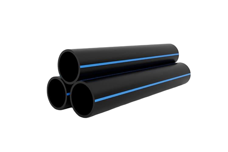
HDPE answers seawater's central problem — corrosion — completely. Polyethylene doesn't corrode in seawater or react with chloride, so it needs no corrosion allowance, no coating and no cathodic protection, where steel and ductile iron corrode hard and lose capacity over time. Its smooth bore resists biofouling adhesion and allows pigging and chlorination cleaning; it's flexible enough to ride waves, currents and seabed movement; its joints are fully fused and leak-free; and it's UV-stable with a multi-decade life. Ballasted with concrete weights, it sits and stays on the seabed.
Where HDPE fits in a desal plant
HDPE appears at several points in a desalination plant, each with its own demands. The open seawater intake draws from an offshore head to the shore — large-diameter and submerged, so external pressure governs. The outfall carries the concentrated brine back to sea, ending in a diffuser. And the multiport diffuser itself disperses that dense brine for dilution. The table maps the main locations and what matters at each.
| Location | Role | Notes |
|---|---|---|
| Open seawater intake | Draw seawater from an offshore head to shore | Large diameter; external/vacuum pressure → buckling-governed |
| Outfall pipeline | Carry concentrate (brine) back to sea | Usually low-pressure / gravity; ends in a diffuser |
| Brine diffuser | Multiport section for near-field dilution | HDPE main with riser branches + duckbill nozzles |
| Brine / transfer lines | Plant-side concentrate & transfer piping | PN-rated where pumped |
| Intake head / screens | Velocity-capped inlet, debris exclusion | Often HDPE or HDPE-attached |
The intake line: buckling & choosing SDR for collapse
The submerged seawater intake is governed by a design case many buyers overlook: external-pressure buckling. Under vacuum and hydrostatic load, the pipe can collapse before it ever reaches an internal-pressure limit — so the wall is sized for collapse resistance, which means choosing the SDR for buckling rather than just for PN. Critical collapse pressure falls sharply as SDR rises, and it must be checked against the long-term (aged) modulus with a safety factor, not the short-term strength. Spec the intake by its collapse case.
Marine installation: the float-and-sink method
The signature HDPE marine technique is float-and-sink. The pipe is fused into a long string onshore, fitted with concrete ballast collars, and floated out to position on the surface while still air-filled. Then it's flooded slowly from the shore end — the sinking rate controlled by bleeding air through a valve — so the string lays down gently onto the prepared seabed. A horizontal directional drill usually handles the shore and surf-zone approach, with seabed trenching in soft sediment and the diffuser bolted on at the end.
Ballast & anchoring
Because polyethylene is only slightly denser than water and floats when air-filled, marine HDPE must be ballasted to stay on the seabed. Concrete weight collars give it negative buoyancy, and their size and spacing are designed to resist not just the pipe's buoyancy but the drag of storm currents and wave action over its life. Under-designing the ballast and anchoring is a common failure mode — the line lifts or migrates. Weight design follows the marine-installation guidance (PPI Handbook Ch. 10) for the pipe size and SDR.
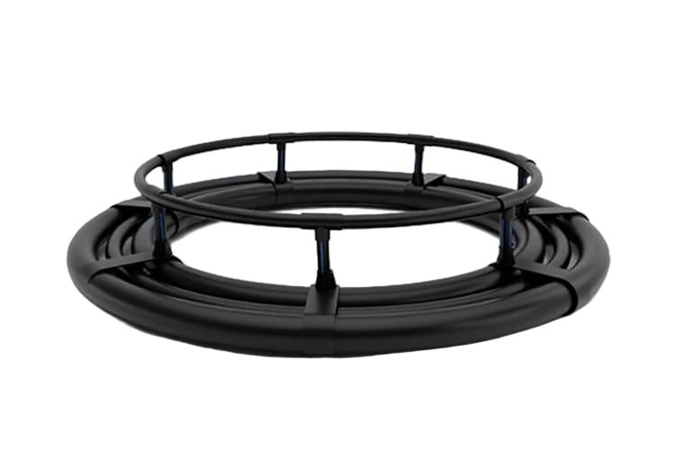
Brine outfalls & multiport diffusers
Desalination concentrate is denser and saltier than seawater — roughly one-and-a-half to two times the feed salinity — so the brine plume sinks, and dispersing it is an environmental requirement. A multiport diffuser does that: a section of HDPE pipe with closely spaced riser branches and nozzles (often duckbill check valves) that drive rapid near-field dilution. Port count, diameter, angle and spacing are tuned to meet a regulatory salinity-rise limit at the edge of the mixing zone, and uniform per-port flow matters — poor riser geometry starves the downstream ports.
Biofouling, chlorination & pigging
Seawater lines foul, and HDPE handles cleaning well. Its smooth bore resists marine-growth adhesion and lets the line be pigged, and it tolerates intermittent shock chlorination at the intake. The honest caveat is the same one that applies to potable systems: continuous high oxidant dosing over many years can slowly deplete the pipe's antioxidants, so where dosing is chronic it's worth specifying a resistant grade — or relying on periodic pigging, a common non-oxidant alternative, a few times a year.
How big can HDPE go? When GRP or steel win
HDPE has a practical diameter ceiling, and it's worth being honest about it. Solid-wall extruded PE100 is commonly available to around 2,000–2,500 mm, and structured-wall or spiral-wound PE with PE100-RC pushes to roughly 2.8 m (the Al-Jubail plant used 2.9 m intake and 2.8 m outfall lines). Beyond that, or where very high pressure or stiffness is needed, GRP, coated steel or lined concrete can win. The honest comparison: HDPE leads on corrosion immunity, marine installation and leak-free fusion; the alternatives lead on the very largest diameters.
| Material | Wins | Loses |
|---|---|---|
| HDPE / PE100 | Corrosion immunity, float-and-sink install, fused leak-free, flexible | Diameter ceiling; needs ballast & buckling design |
| Coated / CP steel | Very large diameter, high pressure, stiffness | Corrodes without perfect coating + CP; heavy |
| GRP | Very large diameter, stiff, corrosion-resistant | Brittle/impact; diffuser joint integrity; harder marine install |
| Concrete / lined steel | Largest diameters, mass stability | Weight; liner/rebar corrosion; no flexibility |
Standards
The PE pipe itself is made to ISO 4427 or EN 12201 in PE100 / PE100-RC material, with AWWA pressure-pipe standards in some markets. Marine pipeline design draws on the PPI Handbook's marine chapter for float-and-sink and ballast, and on broader submarine-pipeline frameworks such as DNV for the marine engineering — though those frameworks are steel-oriented and are cited as context, not as an HDPE material spec. As always, the buckling and ballast engineering, and the diffuser dilution design, are project-specific.
5 costly mistakes
- Speccing by PN and ignoring external-pressure buckling on a submerged or vacuum intake — choosing too high an SDR, and risking collapse.
- Under-designing ballast and anchoring for buoyancy plus storm currents and wave drag — letting the line lift or migrate.
- Ignoring continuous-oxidant exposure — treating chronic chlorination like intermittent shock dosing.
- Assuming HDPE for the very largest diameters without checking the solid-wall ceiling (GRP or structured-wall may be required).
- Poor diffuser and dilution design versus the environmental salinity-rise limit — wrong port count, angle or spacing, or non-uniform port flow.
References & standards
- [1]Plastics Pipe Institute (PPI) — Handbook of PE Pipe, Ch. 10 — marine installations
- [2]PE100+ Association — PE100-RC in large-diameter sea outfall applications
- [3]ISO — ISO 4427-1 — PE pipes for water supply & pressure sewerage
- [4]DNV — DNV-ST-F101 — submarine pipeline systems (marine framework)
- [5]Sangir — Large-diameter HDPE diffusers for a desalination outfall
- [6]AGRU America — How to create a desalination pipeline system
- [7]Makai Ocean Engineering — World's largest desalination plant pipeline (Al-Jubail)
- [8]IntechOpen — Desalination brine management & outfall design
Frequently asked questions
Need expert advice on your project?
Our engineering team helps utilities, contractors and EPCs specify the right pipe material and SDR for their project. Get a no-obligation technical consultation.
Talk to an engineerRead next
Explore further
Related applications, material comparisons and country buying guides selected for this topic.