Guide
Electrofusion Welding: Procedure & Parameters for HDPE/PE Pipe (2026)
The 10-step procedure — why scraping the oxide layer is the make-or-break step — plus voltage, fusion and cooling parameters, cold-weather rules and QC.
Dr. Wei Liu, P.E.
Senior Engineering Manager · Primepoly
Published: Jun 7, 2026
Updated: Jun 7, 2026
13 min read
Electrofusion is the most forgiving way to join polyethylene pipe in tight spaces, repairs and tie-ins — and the most unforgiving about surface preparation. The fitting does the heating; the operator's job is to present clean, oxide-free, well-aligned pipe and let the control box deliver the programmed energy. Get the scraping and clamping right and the joint is leak-free for the life of the pipe; skip the scrape and it will fail. This guide sets out the procedure, the parameters and the checks.
What is electrofusion (and when to use it)?
An electrofusion fitting — a coupler, reducer, elbow, or saddle/tapping tee — has a resistance-wire coil moulded into its bore. A control box passes current through the coil; the resistive heat melts the fitting bore and the adjacent pipe wall, and the two melts fuse into one continuous joint as they cool under restraint. Electrofusion shines where butt fusion is impractical: repairs, tie-ins, congested trenches, joints between slightly different SDRs, and branch connections onto live, in-service mains.
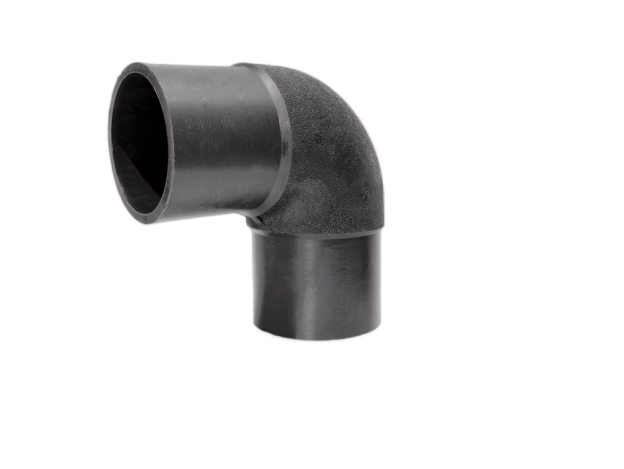
Electrofusion fitting types
The common EF fittings are straight couplers (the workhorse), reducing couplers, elbows and tees, and saddle/tapping tees that fuse onto the side of a main to create a branch — often on a pressurised line. Each fitting carries its own barcode encoding the fusion parameters, and each has melt indicator pins that rise to show the coil reached fusion temperature.
Governing standards
Electrofusion fittings and practice are covered by several standards — the fitting itself by ISO 8085-3 / ISO 4437 (gas) and EN 12201-3 (water), and the welding process by DVS 2207-1 (Europe), ASTM F1290 (USA) and WIS 4-32-08 (UK water), with PPI TR-49 and MAB-01 as the widely used generic field procedures. They agree on the essentials below; the fitting maker's published instructions always take precedence.
| Standard | Scope |
|---|---|
| ISO 8085-3 / ISO 4437 | EF fittings (gas; 8085 superseded by 4437) |
| EN 12201-3 | PE fittings for water (Europe) |
| DVS 2207-1 | Heated-tool & electrofusion welding of PE (Europe) |
| ASTM F1290 | Electrofusion joining practice (USA) |
| WIS 4-32-08 | Fusion jointing of PE pressure pipelines (UK water) |
| PPI TR-49 / MAB-01 | Generic EF field-joining procedures |
Tools & equipment you need
A correct electrofusion joint needs: a rotary/peeling pipe scraper (that removes a controlled, continuous curl — not sandpaper, files or rasps), an approved PE cleaner or high-purity isopropanol with lint-free wipes, alignment and re-rounding clamps to hold the joint without stress, and an electrofusion control box with the right output and a barcode scanner. Cold conditions may also call for a shelter or tent.
Step-by-step electrofusion procedure
The procedure is ten steps; two of them — scraping (Step 4) and cooling (Step 9) — are where most failures originate. Follow them in order and record the joint.
- Cut the pipe square and deburr the end, inside and out.
- Check ovality and re-round the pipe with clamps if it is out of tolerance — an out-of-round pipe leaves gaps at the coil and cold spots.
- Measure and mark the insertion depth on the pipe (about half the fitting length per side for a coupler), and mark the scrape zone to extend slightly past it.
- Scrape off the entire oxidised surface layer over the whole fusion zone with a rotary/peeling scraper — NOT sandpaper. This is the single most critical step: oxidised PE will not fuse.
- Clean the scraped zone and the fitting bore with an approved PE cleaner / isopropanol on a lint-free wipe, let it fully dry, and do not touch the prepared surface again.
- Assemble the fitting onto the pipe to the insertion mark and fit alignment/restraint clamps so the joint bears no bending or axial load.
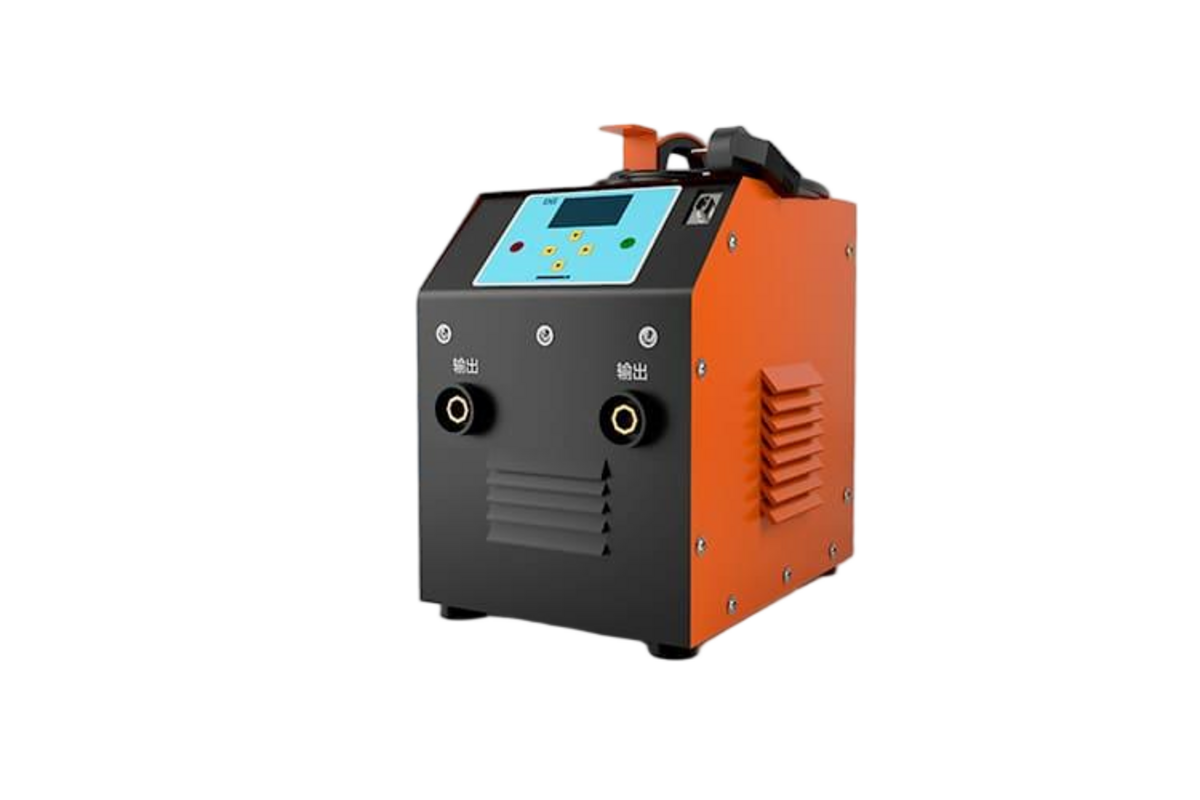
- Connect the control box and scan the fitting's barcode — it sets the fusion voltage and time automatically; the box also checks coil continuity.
- Run the fusion cycle; the box delivers the programmed energy and the melt indicator pins rise to confirm the coil reached fusion temperature.
- Leave the joint clamped and undisturbed for the full cooling time printed on the fitting/box — moving or unclamping early is a top cause of failure.
- Record the joint: fitting size, brand and batch, operator, fusion and cooling times, ambient temperature and joint ID — ideally auto-logged by the box for traceability.
Parameters explained: voltage, fusion & cooling time
Electrofusion parameters are encoded in the fitting's barcode, not chosen by the operator. Coupler fusion voltage is commonly around 39.5 V (the industry range runs roughly 39.5–48 V, with lower voltages on some large or saddle fittings), while fusion time and cooling time vary by fitting size, brand and ambient temperature. The melt indicator pins confirm that energy was delivered — they are a go/no-go signal, not a guarantee of a perfect joint.
Cold-weather & ambient compensation
Lower ambient temperature means the coil needs more energy and time to reach fusion, so cold weather extends the required fusion time. Some control boxes read ambient temperature and compensate automatically; others require the operator to apply the maker's correction, and many specs set a working window with tenting or pre-heating below freezing. Always follow the fitting maker's temperature limits and corrections — guessing in the cold causes under-fusion.
Quality control & joint inspection
Inspect every joint: the melt indicator pins should be up, continuous scrape marks should be visible across the full fusion zone, and the data log should be complete. Because non-destructive testing options for electrofusion are limited, the backbone of EF quality is process control plus destructive verification — peel/decohesion and crush tests on sample or qualification joints, checking for a ductile (not brittle) failure mode. Keep the data log for traceability.
Pre-fusion go / no-go
5 common electrofusion mistakes
- Failure to scrape — or scraping only part of the zone, or using sandpaper. The oxidised PE skin must be fully and uniformly removed with a rotary/peeling scraper, or the joint won't fuse. This is the number-one cause of EF failure.
- Contaminating the prepared surface — touching the scraped zone, using a dirty or treated wipe or the wrong solvent, or fusing before it dries (and rain/moisture).
- Wrong or short insertion depth, so part of the coil isn't covered by pipe — giving a weak or unfused joint.
- Disturbing the joint during fusion or cooling — unclamping or loading it before the full cooling time elapses cracks the still-soft melt.
- Ignoring ovality and ambient temperature — an out-of-round pipe (no re-rounding clamp) and uncompensated cold weather both cause cold spots and under-fusion.
Glossary
- Electrofusion (EF)
- Joining PE pipe with a fitting that has an embedded heating coil; a control box energises the coil to melt and fuse the fitting to the pipe.
- Oxide layer / scraping
- The oxidised PE surface skin that prevents fusion; it must be fully removed with a rotary/peeling scraper over the whole fusion zone before welding.
- Tapping tee / saddle
- An EF fitting fused to the side of a main to create a branch, often on a live, in-service line.
- Melt indicator pins
- Pins on the fitting that rise during fusion to show the coil reached fusion temperature — a go/no-go signal.
- Fusion / cooling time
- Energy-on time and the mandatory undisturbed cooling time, both set by the fitting barcode and varying with size and ambient temperature.
- Re-rounding clamp
- A clamp that restores a round cross-section to out-of-round pipe so the coil contacts the pipe evenly and avoids cold spots.
References & standards
- [1]ASTM International — ASTM F1290 — electrofusion joining of polyolefin pipe and fittings
- [2]Plastics Pipe Institute (PPI) — TR-49 — generic electrofusion user guide
- [3]PPI Municipal Advisory Board — MAB-01 — generic electrofusion procedure for field joining of PE pipe
- [4]Water UK — WIS 4-32-08 — fusion jointing of PE pressure pipelines (PE80/PE100)
- [5]DVS (German Welding Society) — DVS 2207-1 — heated-tool & electrofusion welding of PE-HD
- [6]PE100+ Association — Electrofusion: a simple method of joining PE pipes
- [7]Georg Fischer — Central Plastics — electrofusion installation & training manual
- [8]Radius Systems — Joining PE pipes in cold temperatures (electrofusion)
Frequently asked questions
Need expert advice on your project?
Our engineering team helps utilities, contractors and EPCs specify the right pipe material and SDR for their project. Get a no-obligation technical consultation.
Talk to an engineerRead next

Explore further
Related applications, material comparisons and country buying guides selected for this topic.